
Materials Handling & Accessories
Eddy Current , Ultrasonic and Flux Leakage inspection requires appropriate mechanics, controls and accessories to handle the test material and house the test sensors. MAC has designed a range of standard and custom handling systems that integrate mechanics with the test systems and production line to ensure the most accurate test results.
MECHANICS FOR MOUNTING TEST SENSORS
Rotary Mechanics for Eddy Current Systems
Where rota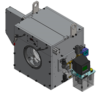 ting eddy current probes are being used, they are housed in a rotary headplate, mounted in rotary mechanics that include a motor for spinning the headplate with its test prob
es around the material under test. Current rotaries feature continuously variable high speed rotaries (1800 – 6000 RPM), capable of handling test material up to 191 mm (7-1/2″) diameter.
Coil Platforms for Eddy Current Systems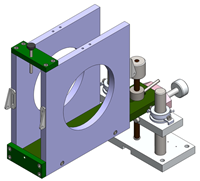
Proper positioning of the eddy current test coil with respect to the material being t
ested is a key ingredient of any eddy current inspection system.
MAC Coil Platforms are:
- Adjusted vertically and horizontally for proper alignment
- Encircling (throughput) or tangent (sector)
- Designed for various applications, including:
- cylindrical and shaped material
- magnetic and non-magnetic material
- Designed for sizes up to 235 mm (9.25″) diameter for encircling test coils
- Sizes up to 304.8 mm (12.0″) diameter for sector (tangent) coils
Rotary Mec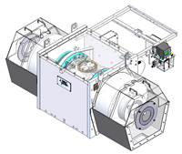 hanics for Ultrasonic Systems
MAC’s Echomac® UT Rotary rotates ultrasonic transducers for shear-wave and compression-wave configuration at high throughput speeds. Standard models handle material from 6.3 mm to 500mm (1/4″ to 9″) at test speeds up to 400 fpm, depending on the size and condition of the test material.
Rotary Mechanics for Flux Leakage Systems
Flux leakage test systems incorporate rotating test probes, mounted in a rotary headplate assembly. Current systems are available to handle up to 500mm diameter and 19 mm (3/4″) wall thickness. Picture shows the headplate with test probe assemblies and magnetizing pole pieces for detecting longitudinal defects. Rotary mechanisms designed for detecting transverse defects are also available.

TEST BENCHES & DRIVES
“V” Roll Test Benches
The various coil platforms and rotary mechanics described above can be mounted on a MAC test bench which aligns the test material with the test sensors. MAC’s standard test bench utilizes 120 degree “V” rolls and pinch stands to support and position the test material. The fixed bottom “V” rolls, in conjunction with a flat top roll, provide 3 points of contact and ensure firm support for the test material, eliminating vibration that can cause false indications. Automated or manual controls adjust the pinch stand rolls to the size of the test material. Drive Mechanisms provide forward movement of the test material through the coil platforms and rotary mechanics where needed. Individual elevating platforms are usually included on the test bench for positioning larger rotary mechanics. 90 degree rolls are also available for square material. Auto diameter controls are available to automate adjustments of the testers and drives when the test material diameter is changed.
“V” Roll Pinch Stands
Automated or manual Pinch Stands help eliminate vibration that can interfere with the test, and ensure that the test material is properly positioned as it enters and leaves the test sensors. Pinch stands can be mounted on a test bench, or directly on a production line.
Constant Center Triple Benches
MAC’s subsidiary M A Nordic offers a constant center, automated triple drive and table to accommodate several testing systems, including stationary or rotary eddy current, flux leakage, or ultrasonic instruments. A constant center triple drive roll bench is another option for mounting the various mechanical components for MAC test systems. The bench eliminates vibrations from the test material that can cause false reject signals. A triple pinch is mounted between each test station on the bench. Each pinch, driven by a separate AC motor, uses three hardened steel rolls to center the test material. A frequency converter controls the AC motors to guarantee equal speed for all of the pinches. Slide mechanisms are available to allow access to test heads for off line setup and maintenance.A single point adjustment of the table and diameter of the triple driving and centering guide aligns the table and testers with the production line. It is especially applicable to products such as tubes with badly formed ends, upset pipe or difficult straightening applications.
FEED SYSTEMS
Modular Design
The Feed System’s modular design permits quick assembly into many configurations to handle various lengths of material, and allows for later additions or changes. Both round and hexagonal material can be accommodated. Models are available for handling bars or tubing ranging in size from 1/8″ (3.18mm) up to 7-1/2″ (191mm).
Typical Application:
- Automated feeding, rejecting and handling of bars and tube in ndt test stations.
